Two colour metasurface hologram: PlanOpSim design example
Holograms have always appealed to the imagination of both scientists and the general public. But wide angle and full colour holograms has proven elusive despite many years of research. In this article we explore some of the possibilities for making metasurface holograms and how they can contribute to this lofty goal.
Reading time: 7 minutes Written for: optical engineers, photonics engineers, researchers, technology scouts Extra-relevant if you are interested in: metasurfaces , holograms, colour multiplexing, polarization
How can metasurfaces improve holography
Meta-surfaces have a few distinct advantages compared to other techniques used to generate holograms:
●Intrinsically small pitch: leads to wide angle holograms
●Multi-level control of the phase with a single thickness of the structured layers
●Functionalization of the metaatoms for different wavelengths and/or polarization
As a demonstration, a step by step design of a two wavelength metasurface hologram is made using the PlanOpSim software. In this example we select 2 common laser wavelengths 532nm (green) and 632nm(red). The design and simulation are carried out in the PlanOpSim software, combining full wave calculations (RCWA), fourier optics and computer generated holography (CGH) simulations.
The design process consists broadly of these steps:
●Determine the appropriate unit-cell size from the transmission and opening angle requirement
●Define a library of metaatoms that independently control the phase of both wavelengths
●Identify wavefront shapes for both wavelengths
●Optimize the meta-atom placement to match both wavefront shapes
●Verify the projected images compared to the target images.
Meta-atom library for two colour hologram
The largest unit cell pitch we can use for our metaatoms is determined by two requirements: the opening angle specification and suppressing the diffraction losses to reach high zero order transmission. Both requirements demand that the pitch is small enough. The maximum opening angle θ that can be achieved with a hologram with a pitch P is given by the relation:
For a typical pixel on a spatial light modulator (SLM) the pixel pitch is of the order of a few µm. For a reference system with a red laser with 632nm wavelength and a 5 µm pixel pitch this means the opening angle is limited to 3.7°. In this example we target an opening angle of 20°. This means that the pitch should be smaller than 1.08 µm.
To suppress diffraction losses the first diffraction loss should be larger than the wavenumber in both the substrate and air. For this reason the pitch is restricted to at most λ/n= 0.532/1.48 =0.36 µm. So the sub-diffraction requirement is the most restrictive condition in this case.
For the next simulations the unit cell was set to 0.36 µm with a structure height of 0.8 µm. The nanostructures consist of Titanium dioxide (TiO2) on a fused silica (SiO2) substrate. The opening angle corresponding to this pitch is 47° and 61° for 532 and 632nm respectively.
Having set the pitch, we now have to devise a set of nano-structures that can control the phase for 532nm and 632nm independently. An elegant way to achieve this is by utilizing polarization multiplexing. The working mechanism is to choose structures that exhibit form birefringence, so that a different phase is accumulated by TE and TM polarized light propagating through the structure. By designing structures for two orthogonal polarizations of respectively 532 and 632nm, instead of the same wavelength, we will obtain independent phase control for those wavelengths via the polarization.
As a basic structure we use a “+” shape where the vertical and horizontal arms are separately modified to influence the TE and TM polarization. Within this example the “+” shape is used but the principle can be straightforwardly applied to any structure that is not symmetric to a 90° rotation.
Figure 1: Asymmetric cross structure used to control phase of 2 orthogonally polarized beams.
The remaining task is to vary the 4 structural parameters (width and length for x and y indicated in Figure 1) to find a set of high transmission phase sampling nanostructures. For this purpose we simulated 64000 individual configurations using the RCWA algorithm in the PlanOpSim MetaCell module. Figure 2 shows a mapping of these structures transmitted phase for 632nm/TM and 532nm/TE incidence. Each dot represents one nano-structure with its transmission indicated by the color and size (large red dots have high transmission, small blue dots show low transmission).
Figure 2: Transmitted phase for 532nm TE and 632nm TM incidence. This library is used to select metaatoms for independent phase control in the metasurface hologram.
From figure 2 it is clear that our structure library can cover most of the required phase combinations. There are 2 regions where the library shows only a sparse coverage in the lower left and lower right corners. The coverage could be further improved by selecting a larger structure height, using a higher refractive index contrast or (potentially) additional structure shapes. It should be noted that larger heights (and therefore aspect ratios) are more difficult to manufacture. While increasing refractive index contrast is difficult since TiO2 already is one of the highest refractive index materials available in the visible spectrum.
From this large library, 64 (8×8) metaatoms were selected to support 8 independent sampling levels of the phase for 532nm and 632nm. The selected metaatoms are shown in figure 3.
Figure 3: Selected metaatoms and their phase distribution 532nm TE and 632nm TM. This group allows to recreate pairs of phase values for 532nm and 632nm within the metasurface wavefront.
Dual wavelength metasurface component
In order to build our holograms we now have to place the metaatoms so that their projected intensity matches our desired hologram images. This design question consists of 2 important questions:
1.Which phase profile at the metasurface will produce the desired target image
2.How can the phase profile be replicated using our meta-atom library
For a two colour hologram the first step can be done independently for each wavelength. While in the second step our metasurface must simultaneously replicate both phase profiles.
Phase-profile calculation
Calculating the phase profile is a well known problem for computer generated holograms. In this example we have used the iterative fourier transform algorithm (IFTA) also known as the Gerchberg-Saxton algorithm. The IFTA transforms an input far field amplitude into a near-field phase profile with uniform amplitude. In this way a high efficiency phase-only hologram is created.
The IFTA was run directly in the PlanOpSim softwares MetaComponent module by defining a far field target. Two targets have to be specified, one for each wavelength. The figure below shows the input settings and images used for the targets. The 2 images for red and green are completely different. Both have been converted to greyscale values representing intensity of the two wavelengths.
Figure 4: Definition of separate target projected images in PlanOpSim software.
Meta-atom arrangement
After determining the phasefront, the design continues by placing the metaatoms. For our design we choose a 1×1 mm meta-component this corresponds to 7.7 million metaatoms. The metaatoms positions are determined using weighted least square fitting of the phasefront. This procedure simultaneously minimizes the error for both wavelengths and, if possible with our meta-atom library, will produce a good approximation of the phasefronts obtained via the IFTA calculation. In figure 5 the resulting GDS file is displayed.
Figure 5:GDS layout of the designed metasurface(close-up). The total design area is 1x1mm.
Projected images
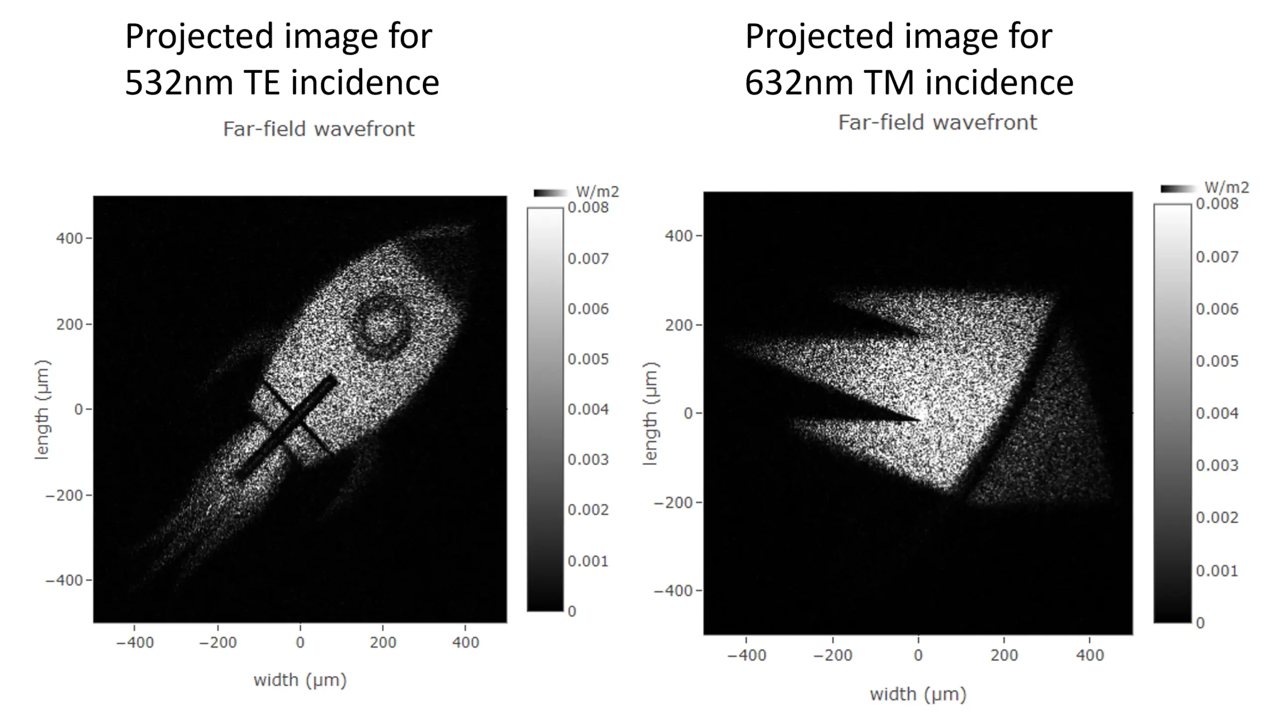
To verify the designed metasurface we simulate the projected image at the design distance of 1.37mm and opening angle of 20°. Figure 6 shows the simulated intensity for 532nm and 632 nm respectively. The projected images reproduce the target. The projected image does have a noticeable speckle noise. This is a typical phenomenon for phase-only holograms. The calculated transmission is respectively 68% and 90% for 532 and 632nm, 43% and 64% of the incident light are within the target illumination area.
Figure 6: Simulated hologram projection for 532nm and 632nm from the designed metasurface.