Reading time: 10 minutes
Written for: optical engineers, photonics engineers, researchers, technology scouts. Extra-relevant if you are interested in: meta-surfaces, spatially varying polarization (e.g. S-plate, Q-plate, J-plate), HWP, birefringent meta-material.
Application examples: Structured light for lithography, Optical tweezers or microscopy; radially symmetric beams for high quality laser cutting.
This article was published as part of an ongoing series of background articles on design and applications of meta-surfaces: https://planopsim.com/news-background/
In this example we will design a meta-component with the focus on creating a design with spatially varying polarization. In this example we will specifically simulate a radially polarization converting meta-component (S-plate [1]) within the PlanOpSim software though the design steps can be used as a basis for azimuthal polarization, Q-plate [2], J-plate [3],…
The simulation of this meta-component consists of two main steps: First find meta-cells which are applicable at the local level, and second, organise these meta-cells into a meta-component.
Meta-cell
simulation
Selecting the correct meta-cells is the most critical step in the design. For each unique local conversion of polarization in the meta-component there should be a selected meta-cell. Conversion of polarization can be done with a birefringent meta–material. While a normal birefringent material gets its birefringence from asymmetry in the molecules (liquid crystal) or from asymmetry in the crystal structure, a birefringent meta–material gets its birefringence from the asymmetry of the meta-cell [4]. This is sometimes called structural birefringence. In the case of a radially polarization converging meta-component, designed for a specific wavelength, we need to select meta-cells covering the polarization rotation from linear polarization (e.g. TE) to all linearly polarized output states. To evaluate this condition properly we will use the Stokes parameters [5]. Specifically the S1 and S2 parameters which express the degree of linear polarization. We want to generate any combination of Stokes parameters for which S1²+S2² = 1 circle on the Poincaré sphere. The parameter tells us the degree of ellipticity which we want to minimize. This example also requires a second set of meta-cells covering the S1²+S2² = 1 circle but with a 180 degree phase shift.
The easiest way to create a meta-cell group covering this circle is a meta-atom acting as half wave plate (HWP) and rotating it over 180 degree in small steps. Note: Rotating the rectangular pillar slightly changes its properties as HWP due to the (non radially symmetric) square meta-cell borders. Small rotation dependent adaptations to the pillar might be needed for the best quality. In this example case we will neglect this effect.
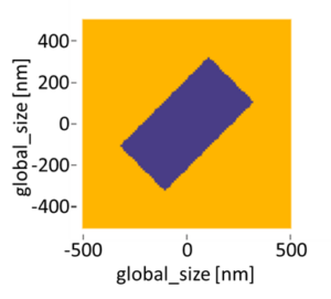
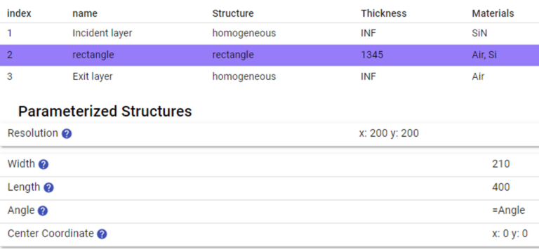
From the article “How to set up the basics: Half wave plate for 1700 nm PlanOpSim design example” we can select a suitable half wave plate meta-cell designed for 1700nm: a rectangular silicon pillar of 210nm by 400nm rotated over 45 degrees on a base layer of SiN within a meta-cell of 1000nm by 1000nm, as visualized in Figure 1.
We simulate this meta-cell when rotating the pillar and plot its Stokes parameters.S0 is the total transmission intensity and defined by the absolute value of the power coefficient of the total polarization, the other Stokes values can be directly selected within the PlanOpSim software.
In Figure 3 all four Stokes parameters are visualised in function of the rotation of the rectangular pillar. From the transmission we can verify the transmission efficiency which is for this meta-cell over 80%. From S1 and S2 we can conclude that, with a 180 degree rotation of the pillar, we have covered 2 times the S1² + S2² =1 circle. The Stokes parameters do only show the polarization, but not the phase.

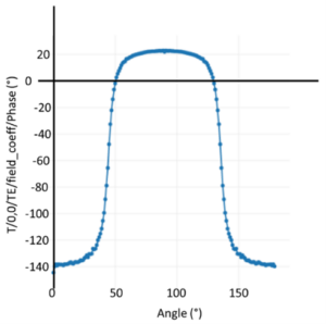
To cover all necessary conversions, we need to check if these two circles have a 180° phase shift. This is not directly possible from the Stokes parameters but can for example be done by visualizing of the TE phase, as shown in Figure 4, which shows that we indeed cover the S1²+S2²=1 circle two times with roughly 180 degree phase shift. From S3 we can conclude that the output polarization is not perfectly linear but contains an elliptical component. Further improvement of the meta-cell, by reducing S3, increasing S0 and matching the 180 degree phase shift better is outside the scope of this example. Here we create a meta-cell group of 36 meta-cells where we change the angle going from 0 to 180 degree in steps of 5 degree.
Meta-component

To organize the meta-cells created in the previous section into a meta-component with spatially varying polarization, we have to define the desired near field wavefront target. In the PlanOpsim software we will implement this as 2 two targets which will be simultaneously optimized for, one target for TE and one target for TM. For a linear polarization with electric field amplitude E under an in-plane angle theta we need a near field wavefront with: (with TE the polarization in the x direction, calculated from the x-axes):

For a radially polarized beam, the polarization angle theta is defined as:

To implement this target in PlanOpSim we create two
targets: TE and TM, both with input polarization (‘Set point’) TE polarization but
with a different
output polarization, as visualized for TM in Figure
6.
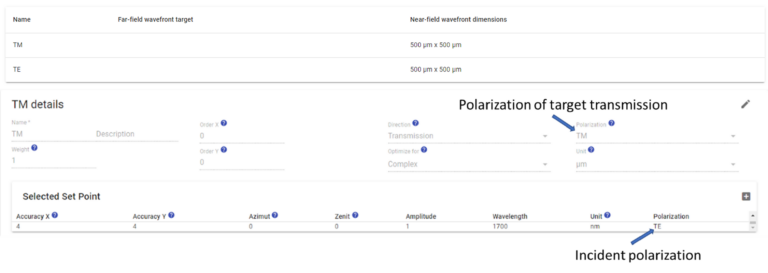
For the TE target and the TM target we need to define the
near field wavefront defined by (1) and (2), respectively. This can be easily
done by the python-based generation code as visualized in Figure
7. Note: the amplitude in the
PlanOpSim software is assumed to be positive, a pi phase shift should be used to set negative values.

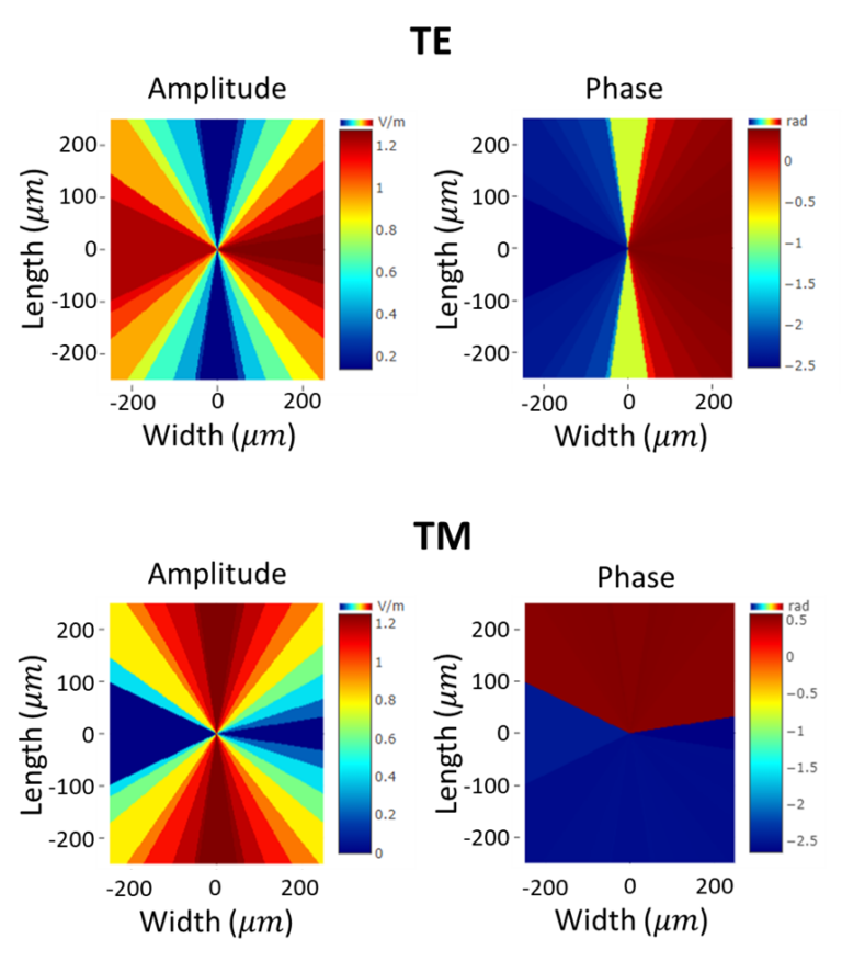
In Figure 8, the near field wave fronts for both TE and TM are visualized. A good check is that the phase jumps are present where the amplitude is 0, meaning that there is no physical abrupt change in the design.

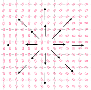
The PlanOpSim software will create the meta-component design based on these two targets. When finished, the GDS file can be downloaded. A visualization of the centre part in KLayout is shown in Figure 9.
Analysis of the meta-component can be done directly within the PlanOpSim software. In Figure 10, the TE and TM transmission near field are visualized. Since we only selected 36 meta-cells there is a clear step each 10 degree in the design. The quality of the meta-component can be improved by selecting more meta-cells.
In postprocessing we made a quiver plot of the polarization vector (real part of the electric field) for 4 different moments in time (phase delay 0°, 45°, 90°, 135°), visualized in Figure 11. In general, we can conclude that this quick design effectively creates the desired radial polarizations. Two main imperfections are the angular discretization and non-ideal phase distribution. The angular discretization is still visible, as discussed, we only included 36 meta-cells for this design which directly leads to a 10 degree discretisation of the angle. A strong improvement can be made by including more meta-cells. The phase distribution is not ideal. It is clear from the quiver plot with a phase delay of 45 degree that the left side lags compared to the right side. To address this, we should improve the phase delay of the meta-cells themselves. From Figure 4 we see that the phase profile is indeed not perfect. We would like to have linear polarization in all angles, and this two times with a 180 degree phase shift. What we actually have is only a 160 degree phase shift and a rather slow transition. With this in mind the dimensions of the meta-cell could be tailored further.

Conclusion
In this design example we successfully designed
a radially polarization converting meta-component. The same meta-cells could be
used to convert a uniform linear polarization into any spatially varying
rotated linear polarization by changing the near field phase front target. In a
very similar way one can create all kind of wave plates ranging from simple
half wave plates and quarter wave plates to complex wave plates such as
Q-plates and S-plates.
Further reading
B. S. Bhargava Ram, Paramasivam Senthilkumaran and Anurag Sharma, “Polarization-based spatial filtering for directional and non directional edge enhancement using an S-waveplate,” Applied Optics, vol. 56, pp. 3171-3178, 2017. |
L. Marrucci, “The q-plate and its future,” Journal of Nanophotonics, vol. 7, no. 1, 2013. |
H. Zhou, S. Fu, Y. Zhai, C. Yin and C. Gao, “Spatial light modulator-based programmable J-plate for the arbitrary spin-to-orbital angular momentum conversion of lights,” Applied physics B, vol. 42, 2019. |
Y. Li, J. Zhang, H. Ma, J. Wang, Y. Pang, D. Feng, Z. Xu and S. Qu, “Microwave birefringent metamaterials for polarization conversion based on spoof surface plasmon polariton modes,” Scientific Reports, vol. 6, no. 34518, 2016. |
N. Viswanathan, S. Chandran Thodika and R. Pandey, “Spatially varying polarization singular pattern: degree of coherence,” Proc. SPIE, vol. 93790F, 2015. |

