An attractive feature of meta-surfaces is the ability to encode different functionalities for different incident light, for example wavelength or polarization selective behaviour. This can be achieved by selecting and placing meta-atoms which have simultaneous but different effects for different incident light beams.
In this example such a multi-functional meta-surface will be designed. The goal is to focus different linear polarizations (TE and TM) on 2 different spots. Using traditional optical components such a setup would require several components: a polarizing beamsplitter, a lens and possibly mirrors for redirecting the beams.
The unique aspect of a meta-surface here is that we can encode a different lens for TE polarized light than for TM polarized light. In this example we will implement an aspheric lens focused at 500 µm from the component surface but moved +50µm off center for TE and -50µm off center for TM polarization.
The design process consists broadly of these steps:
- Define a library of meta-atoms that individually control the phase of both polarizations
- Identify wavefront shapes for both polarizations
- Optimize the meta-atoms placement to match both wavefront shapes
- Verify the polarization splitting and focusing functionality
This article explains how to design such a meta-surface using the PlanOpSim software.
Nanostructure design
The first step of the design is to find a series of nano-structures that are compatible for manufacturing and have independent effects on the phase of the polarization while maintaining high transmission. For the sake of this example we choose a design wavelength of 1550nm. The design principles are similar for other operating wavelengths.
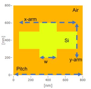
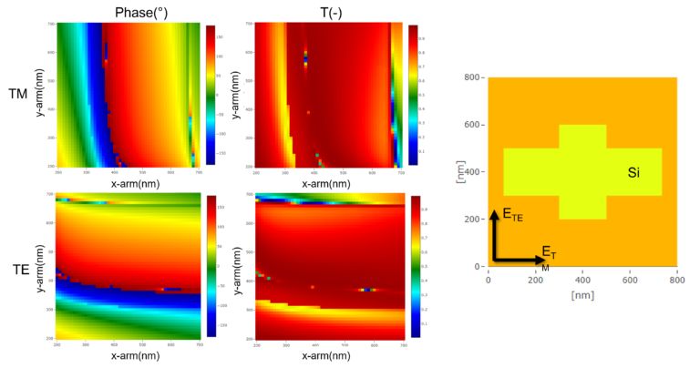
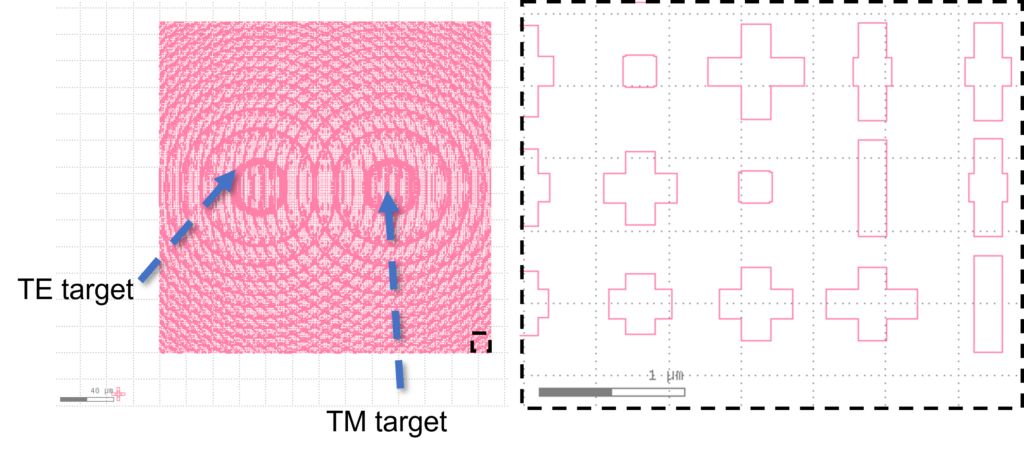
In order to influence the orthogonal TE and TM polarization separately we have to choose structures that are not symmetric to 90° rotation. The structure shown in Figure 1 is suited for this purpose. The length of the horizontal and vertical arms of the structure can be separately changed to have a larger material fill factor in the x and y direction. It is intuitively clear that since the horizontal arms are parallel to the electric field of the TM polarization (vertical arms to TE polarization) that each arm will mainly influence 1 polarization state.
As materials we choose Si structures on a fused silica substrate. Silicon is a natural choice for the 1550nm wavelength since it provides a high index contrast and its manufacturing is well understood.
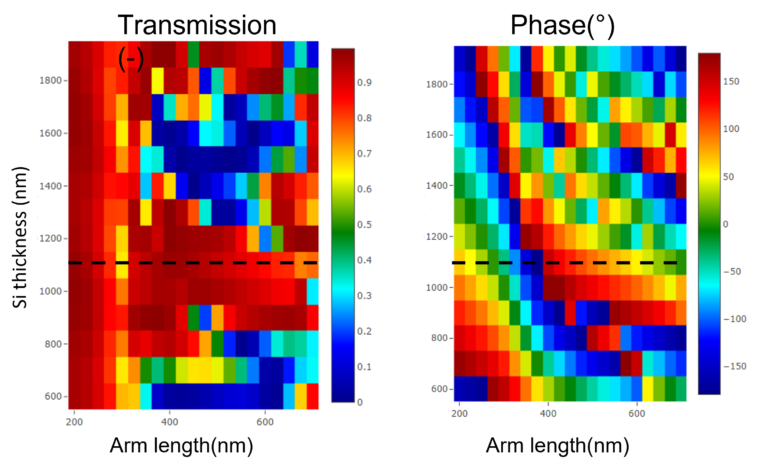
The first choice to be made is which unit-cell dimensions and Si Film thickness to use. To find appropriate choices we will run a combined parameter scan of the unit-cell pitch and height together with the length of the arms. To limit the calculation time both x- and y-arm are considered equal for this simulation.
The figure below shows the transmitted power and phase for various pillar heights. The unit-cell size is 800 x 800nm. From Figure 2 it is clear that for a Si thickness of 1100nm the transmission is at least 65% for all arm-lengths. At the same time the phase varies over 425° degrees (a full 360° from 66° back to 66° and finally to 1°). This combination makes it a good choice for designing polarization controlling nano-structures.
Now we model more closely the influence of the x- and y- arm lengths on both the TE and TM polarization. In the following Meta-Cell simulations the arm lengths are independently changed. Figure 3 shows the effect of the x and y-arm length on the TE and TM polarizations. This simulation confirms the idea that the x- and y-arm primarily influence the polarization state whose electric field is parallel to them. The TM transmission and phase are mostly constant to changes in the y-arm but changes with the x-arm length. Analogously the y-arm length modifies the TE transmission and phase.
From these simulations we can select a library of nano-structures for our polarization splitting meta-lens. For sufficient phase sampling a group of 8 structures with equidistant phase is typically chosen. Because we need to be able to make any combination of TE and TM phase, this becomes a library of 64 structures (8 x 8). To populate the library, we pick the 64 structures that have the shortest Euclidian distance to the complex transmission coefficient corresponding to 100% transmission and a phase of 0-360° in steps of 45°. After this group has been composed, the design can move on to defining the meta-surface itself.
Meta-surface creation
For this example our goal is to separate TE and TM polarization and focus each polarization on a different spot at a 500µm distance from the meta-component. To achieve this we can apply the equation for an ideal spherical wavefront separately to the incident TE and TM polarization:
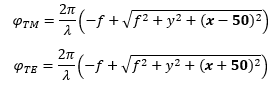
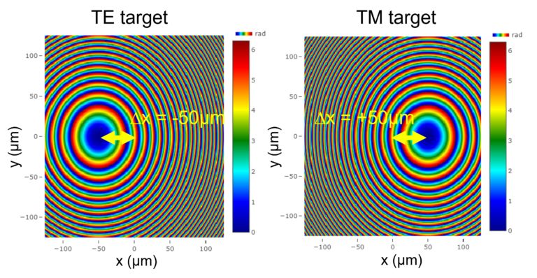
These phase fronts are plotted in Figure 4. Within PlanOpSim software these targets are created by assigning a target to a SetPoint with different polarization. In principle the two targets are independent. The nano-structure library ensures that we can independently reproduce these phase profiles with an 8 step discretization. The nano-structures can now be placed on a grid to produce a meta-surface. Which meta-atom to place is determined by a weighted least square error optimization compared to the phase and amplitude given by the targets.
With the design of the meta-surface completed, it is time to simulate the beam-splitters performance. To see the performance of the meta-surface we simulate the intensity profile at the focal plane for TE and TM incidence. The intensity profile in Figure 7shows that the meta-surface focuses TE and TM at the intended locations. The transmission efficiency of the meta-surface is 89.2% for both polarizations, while the 45% of the incident polarize light is focused in a 20×20 µm spot around the target focal point. For unpolarized incidence the TE/TM ratio in this 20×20µm area is 2342:1.
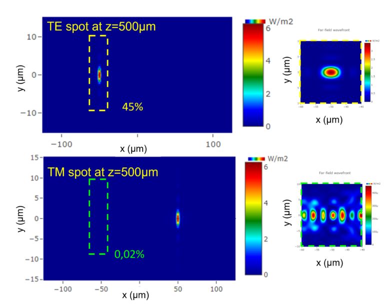
This example showed how to design a multi-functional meta-surface that acts as a polarizing beam splitter and lens simultaneously. The PlanOpSim software was used to design meta-atoms via full-wave solutions and to arrange and simulate a 250×250 µm meta-component. The simulated TE to TM ratio was 2342:1.